EN
EN
 AR
AR
 HR
HR
 BG
BG
 FI
FI
 NL
NL
 DA
DA

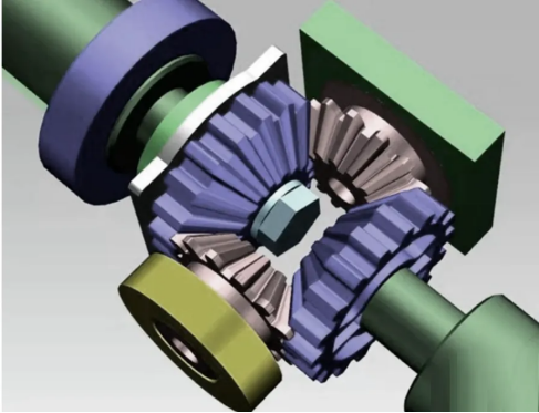
Indispensable gears:Analyzing their key roles in transmission systems
Gears are vital in transmission systems. In automotive, they're key in the transmission. Manual transmissions use gears in the gearbox. Different gear combinations enable speed and torque adjustments for various driving conditions, like accelerating, cruising, or climbing. Helical gears reduce noise and vibration for better driving comfort.
一、 Types and Functions of Gears
1.0. Types of Gears
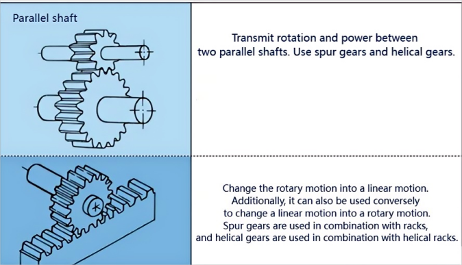
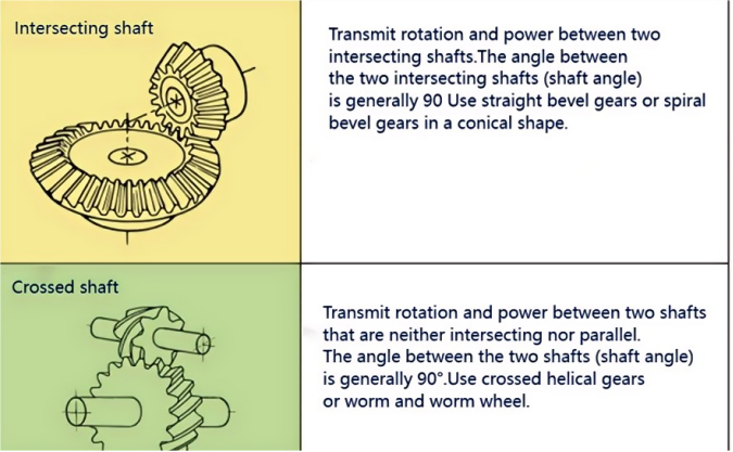
There are numerous types of gears. The most common classification method is based on the gear axis. Generally, they are divided into three types: parallel - axis, intersecting - axis, and crossed - axis. Parallel - axis gears include spur gears, helical gears, internal gears, racks, and helical racks, etc. Intersecting - axis gears include straight bevel gears, spiral bevel gears, zero - degree bevel gears, etc. Crossed - axis gears include crossed - helical gears, worm and worm wheel, hypoid gears, etc.
(Classification and types of gears).
|
Classification of gears |
Type of gears |
Efficiency(%) |
|
Parallel shaft |
Spur gear |
98.0-99.5 |
|
Rack |
||
|
Internal gear |
||
|
Helical gear |
||
|
Helical rack |
||
|
Herringbone gear |
||
|
Intersecting shaft |
Straight bevel gear |
98.0-99.0 |
|
Spiral bevel gear |
||
|
Zero-degree bevel gear |
||
|
Crossed shaft |
Crossed helical gears |
70.0-95.0 |
|
Cylindrical worm and worm wheel |
30.0-80.0 |
The efficiencies listed in this table are transmission efficiencies and do not include losses from bearings, stirring lubrication, etc. The meshing of gear pairs on parallel axes and intersecting axes is basically rolling, and the relative sliding is very small, so the efficiency is high. For crossed-axis helical gears and worm and worm wheel and other crossed-axis gear pairs, since rotation is generated through relative sliding to achieve power transmission, the influence of friction is very large, and the transmission efficiency decreases compared with other gears. The efficiency of a gear is the transmission efficiency of the gear under normal assembly conditions. If there is incorrect installation, especially when the bevel gear assembly distance is incorrect and there is an error in the conical intersection point, its efficiency will significantly decrease.
2.0 The role of gears Gears
Gears must be used in pairs to be effective
2.1 Transmit the power of mechanical motion: There are many gears on many cars. These gears can help the operation of cars or various other machines. For example, like the shifting device on cars and industrial reduction boxes, etc. With the role of gears, they can operate normally.
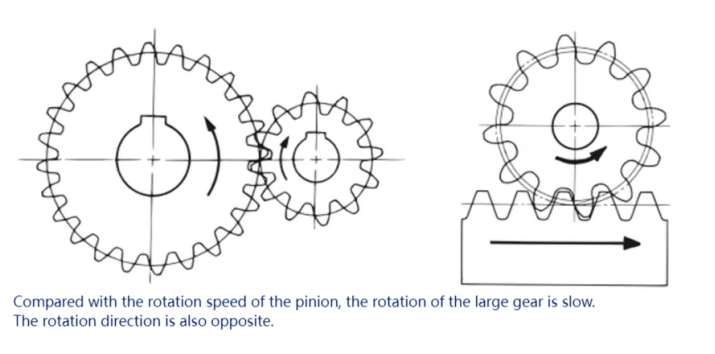
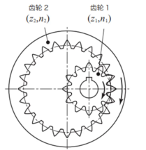
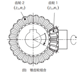
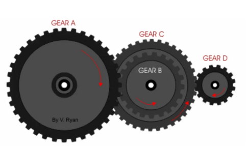
2.2 Change the direction of motion:
The following figure shows the law of changing the direction of motion by different gear combinations.
2.3 Change the speed of motion: Installing the combination of large and small gears on the machine can make the machine accelerate or decelerate quickly, such as reduction boxes and acceleration devices.
2.4 Change the torque or torsion: The combination of large and small gears will change the torque output by the gears; (There is a detailed explanation in the third point below.)
二、 Transmission Ratios and Rotation Directions of Gear Trains
The transmission ratio is the ratio of the angular velocities of two rotating components in a mechanism, also known as the speed ratio. The transmission ratio of component a and component b is i = ωa/ωb = na/nb, where ωa and ωb are the angular velocities of component a and b respectively (radians per second); na and nb are the rotational speeds of component a and b respectively (revolutions per minute).
1.Single - stage gear mechanism: A gear train formed after a pair of gears is meshed is called a single - stage gear mechanism.
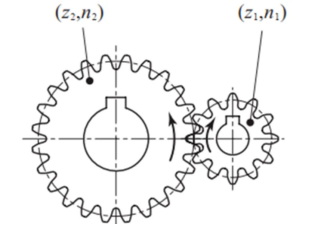
Let the number of teeth of the driving gear of the single-stage gear mechanism be z1, the number of revolutions be n1, the number of teeth of the driven gear be z2, and the number of revolutions be n2. The calculation equation of the transmission ratio is as follows:
Transmission ratio = z2/z1 = n1/n2
According to the value of the transmission ratio, the single-stage gear mechanism can be divided into three categories:
Transmission ratio < 1, speed-increasing gear mechanism, n1 < n2
Transmission ratio = 1, constant-speed gear mechanism, n1 = n2
Transmission ratio > 1, speed-reducing gear mechanism, n1 > n2
2.0 Two-stage gear mechanism: The two-stage gear mechanism is composed of two sets of single-stage gear mechanisms.
The following figure shows the structure of the two-stage gear mechanism.
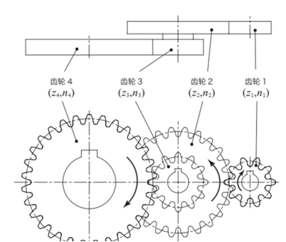
Transmission ratio = z2/z1 * z4/z3 = n1/n2 * n3/n4.
The following is an example of calculating the transmission ratio of a two - stage gear mechanism.
|
Serial number |
Item |
Code |
Formula |
Calculation example |
|
|
Pinion |
Large gear |
||||
|
1 |
Number of teeth (first stage gear) |
Z1,Z2 |
Set value |
10 |
24 |
|
2 |
Number of teeth (second stage gear) |
Z3,24 |
12 |
30 |
|
|
3 |
Rotation (gear 1) |
n1 |
1200 |
- |
|
|
4 |
Transmission ratio (first stage) |
i1 |
Z2/Z1 |
2.4 |
|
|
5 |
Transmission ratio (second stage) |
i2 |
Z4/Z3 |
2.5 |
|
|
6 |
Transmission ratio |
i |
i1×i2 |
6 |
|
|
7 |
Rotational speed (gears 2 and 3) |
n2 |
n1/i1 |
500 |
|
|
8 |
Rotational speed (gear 4) |
n4 |
n1/i |
- |
200 |
|
The unit of rotational speed is rpm. The set value is the value preset by the designer. |
|||||
三、Relationship among Torque, Power and Rotational Speed
Let's first look at some formulas and understand them step by step.
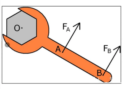
a. In physics, the moment of force, moment of force = force × lever arm (straight line). The formula for calculating the moment of force is M = L×F. The unit of moment of force is Newton - meter, simply called N - m, with the symbol N*m.
Lever arm OA × force Fa = lever arm OB × force Fb.
b. In a rotational state, torque (a special moment of force) = F (force) × r (radius of rotation), that is, the product of the tangential force and the radius of the circle from the force to the point of action. The formula for calculating torque is: M = F*r.
c. The relationship between torque and rotational speed: T = 9550P / n, P = T * n / 9550; P is power in kilowatts (kW); T is torque in Newton - meters (N·m); n is rotational speed in revolutions per minute (r / min). 9550 is a constant.
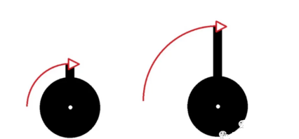
d. The relationship between power and torque and rotational speed: Power (kW) P = Torque (N·m) T × Rotational speed (RPM) n/9550, that is, P = T*n/9550, which can be understood with the following figure.
As can be seen from the gear rotation diagram, the power remains unchanged (ignoring transmission losses), but the rotational speed is reduced. According to power = torque × rotational speed (*constant), the number of times the rotational speed at the wheel end is reduced is the same as the number of times the torque at the wheel end is increased - this is the so-called "wheel torque".
e. The relationship between power and torque and angular velocity: Power P = torque T × angular velocity ω.
Because power P = work W ÷ time t, and work W = force F × distance s, so P = F×s/t = F×linear velocity v. Here v is linear velocity. In an engine, the linear velocity v of the crankshaft = the angular velocity ω of the crankshaft × the radius r of the crankshaft.
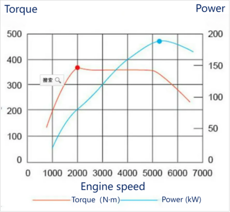
Substituting into the above formula gives: power P = force F × radius r × angular velocity ω. And force F × radius r = torque. Therefore, it can be concluded that power P = torque × angular velocity ω. So the power of an engine can be calculated from torque and rotational speed.
Picture examples.
Supplementary relations: The following are for uniform circular motion.
1.Linear velocity V = s/t = 2πR/T.
2.Angular velocity ω = Φ/t = 2π/T = 2πf.
3.The relationship between linear velocity and angular velocity: Linear velocity = angular velocity × radius, V = ωR.
4.The relationship between angular velocity and rotational speed ω = 2πn (here frequency and rotational speed have the same meaning).
5.Period and frequency T = 1/f.
Main physical quantities and units: Arc length (S): meter (m); angle (Φ): radian (rad); frequency (f): hertz (Hz); period (T): second (s); rotational speed (n): r/s; radius (R): meter (m); linear velocity (V): m/s; angular velocity (ω): rad/s.